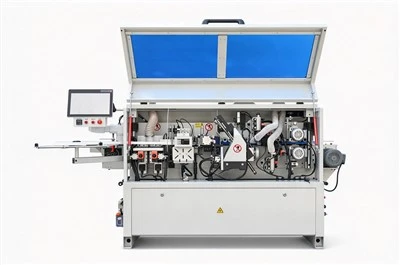
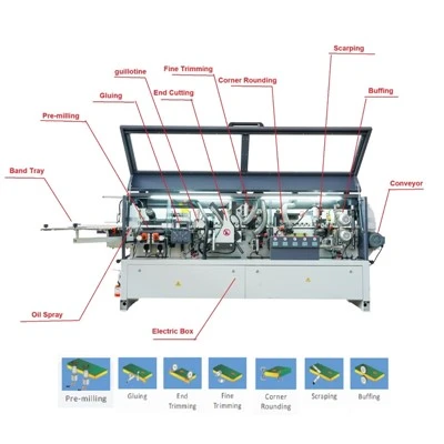
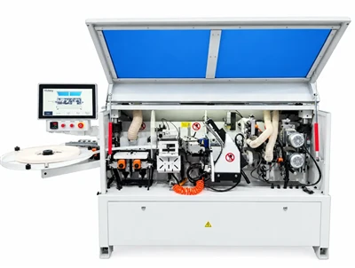
Edge banding machines, a leader in woodworking machinery, have completely revolutionized the traditional manual edge banding process with their highly automated features. Through automation, edge banding machines effectively improve production efficiency and quality. They can continuously complete multiple processes, including conveying, gluing and edge application, cutting, front and rear trimming, top and bottom trimming, top and bottom fine trimming, top and bottom scraping, and polishing, significantly improving the production efficiency and quality of woodworking products.
In woodworking machinery, the process flow diagram describes each step of the woodworking production process and is an indispensable part. It details every link from raw material input to finished product output, including conveying, gluing and edge application, cutting, trimming and edge application, fine trimming, scraping, and polishing. Through this flow diagram, operators can clearly understand the equipment's operating status, promptly identify and resolve problems, and ensure smooth production.
In edge banding machines, the system architecture diagram, showing the equipment's components, also plays a crucial role. It clearly illustrates the various components of the equipment and their interrelationships, including the conveying system, glue application and edge-sealing mechanism, cutting device, edge trimming component, fine edge trimming mechanism, edge scraping equipment, and polishing device. This architecture diagram allows technicians to gain a deep understanding of the equipment's internal structure and working principles, enabling efficient maintenance and troubleshooting.
In the complex system of the edge-sealing machine, the electrical cabinet and mechanism diagrams provide information on the electrical and mechanical components. The electrical cabinet diagram shows the layout and connections of the electrical system, providing technicians with crucial information on circuit routing and component locations. The mechanism diagrams, on the other hand, depict in detail the construction and movement of each mechanical component, helping technicians understand the equipment's kinematic characteristics. The combination of these diagrams makes maintenance and troubleshooting more efficient and accurate.